
Medium-voltage cables operating in harsh industrial environments face far more than simple power-transmission demands. In demanding industrial environments, your cable system must also withstand high temperatures, moisture, chemicals, mechanical stress, and continuous heavy loads without compromising long-term reliability. A mismatch between cable design and operating conditions can accelerate insulation aging, increase maintenance costs, and lead to unexpected downtime.
This guide walks you through the key factors behind choosing the right medium-voltage cable for demanding industrial environments. You will learn how insulation, shielding, ampacity, and jacket materials affect cable reliability and service life. These factors will also influence maintenance needs and operating costs.
Define the Operating Environment First
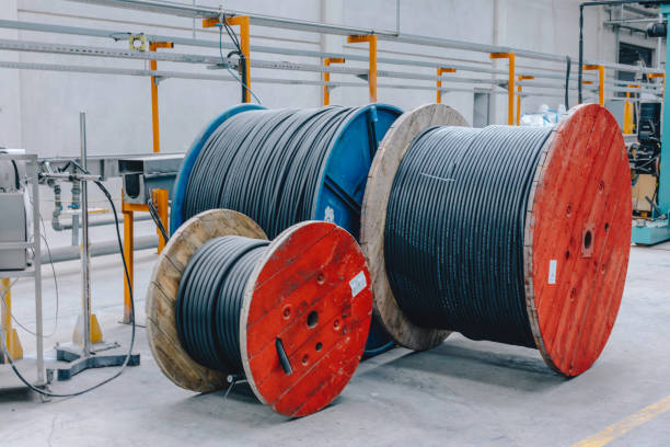
Electrical and Thermal Operating Conditions
Before selecting a medium-voltage cable for industrial applications, you need a clear understanding of the real operating conditions your system will face in service. In 1–35 kV networks, even small errors in defining electrical and thermal behavior can lead to insulation stress, accelerated aging, or unexpected failures that reduce long-term reliability under continuous industrial loading.
The selection process should start with a full evaluation of system fault levels, load profiles, and grounding methods, along with key thermal factors such as ambient temperature and soil resistivity. These parameters directly influence insulation thickness, shielding design, and conductor sizing, helping ensure your cable performs safely under both steady and transient operating conditions.
Mechanical, Chemical, and Compliance Factors
Beyond electrical performance, the installation environment often defines the practical limits of what cable design you can use. Installation methods such as direct burial, duct routing, or exposed runs introduce different mechanical stresses during installation and operation, which you should account for early to avoid damage or premature failure.
In industrial environments, chemical exposure, UV radiation, and moisture can gradually degrade jacket materials and reduce long-term reliability. At the same time, standards such as IEC 60502-2 and UL 1072 set strict requirements for shielding, fire resistance, and mechanical performance, so compliance becomes a key checkpoint in your final selection process.
Determine Voltage and Load Requirements
System Voltage Rating and Insulation Levels
Begin by matching the cable voltage rating to the maximum system operating voltage. Industry standards dictate selecting from baseline classifications like 5 kV, 15 kV, 25 kV, or 35 kV. The rated voltage of the cable must always equal or exceed the maximum operating voltage of the network.
Next, specify the correct insulation level based on the system’s grounding method and fault-clearing capabilities:
- 100% Insulation Level: Apply to solidly grounded systems where ground faults clear in under one minute.
- 133% Insulation Level: Specify for impedance-grounded systems or circuits where faults might persist for up to one hour.
- 173% Insulation Level: Reserve for ungrounded networks exposed to sustained overvoltages.
Coordinate these voltage and insulation specifications with applicable codes. Rely on NEC, IEC 60502-2, and ICEA S-93-639 guidelines to verify that the cable withstands the expected overvoltage profiles and switching surges without degrading the dielectric.
Calculating Load Current and Required Ampacity
Determining the proper conductor size starts with defining the load. Calculate the maximum demand in kVA or kW and convert it to line current. Factor in specific load profiles, power factors, and an appropriate margin for future growth to prevent early obsolescence of the feeder.
After establishing the design current, map it to standard ampacity tables. You must then apply derating factors dictated by the installation environment:
- Conduit fill: Adjust for raceway layout and parallel circuit heating.
- Thermal limits: Account for ambient air and soil temperatures.
- Soil thermal resistivity: Derate for direct burial or underground duct banks based on soil composition.
- Shield configurations: Factor in internal heating generated by circulating currents in grounded metallic shields.
Cable sizing does not happen in isolation. Verify that the continuous ampacity and short-circuit thermal limits of your chosen cable match the interfaced medium voltage equipment. The cable must safely integrate with transformers, metal-clad switchgear, and standard accessories like 200 A load-break elbows or 600 A dead-break separable connectors without exceeding any component ratings.
Need Expert Support for Your Medium-Voltage Cable Project?
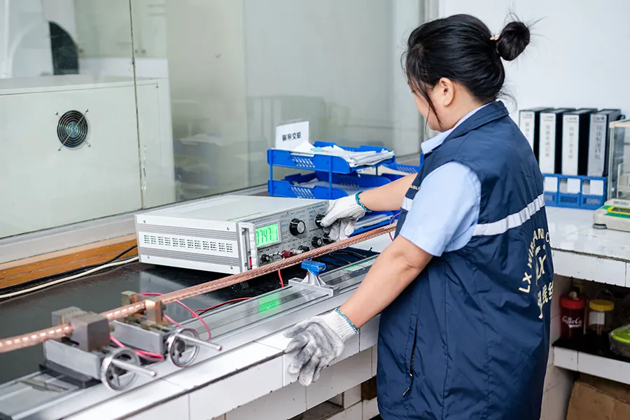
Select the Right Conductor Material
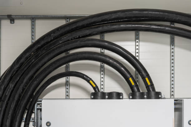
Comparing Copper and Aluminum
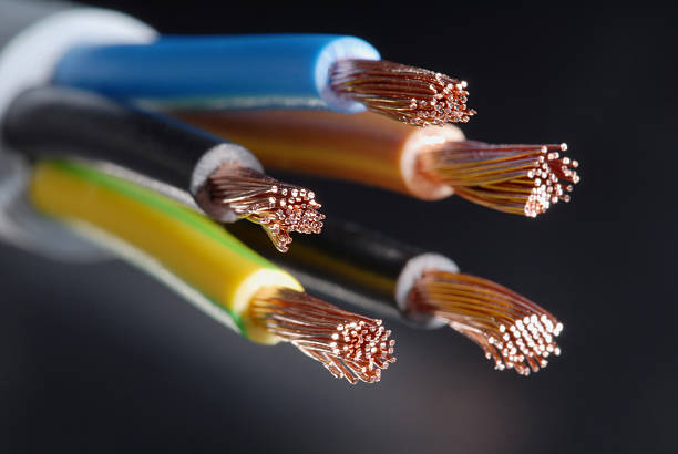
Copper and aluminum dominate medium-voltage cable systems. Copper delivers superior electrical conductivity, which allows you to meet your ampacity requirements with a much smaller cross-sectional area and a tighter cable diameter. That density comes with a trade-off. Copper adds significant weight to the overall cable and drives up your upfront material costs.
Aluminum takes the opposite approach. It drastically lowers material costs and sheds weight, making it the industry standard for extensive distribution networks and long utility cable runs. Because aluminum has lower conductivity than copper, you must upsize the conductor to achieve equivalent current capacity.
Key Factors for Material Selection
You base your final conductor choice on specific project realities. Evaluate these technical and operational factors before signing off on a specification:
- Physical space constraints: Tight conduits, compact switchgear, and limited termination areas often force the use of copper to keep cable dimensions viable.
- Weight and handling: Aluminum reduces pulling difficulty and lowers mechanical tension on the cable during installation, especially across long runs.
- Accessory compatibility: You must match all splices, connectors, and lugs exactly to the chosen conductor material and the system voltage class to prevent termination failures.
- Total installed cost: Look beyond raw material prices. Weigh the upfront savings of aluminum against the physical compactness and enclosure fitting advantages of copper.
Choose Suitable Insulation and Jacket Types
| Component Requirement | Specification Option | Primary Application |
|---|---|---|
| Base Insulation | XLPE, TR-XLPE, EPR | 5 to 35 kV operating voltages |
| Temperature Rating | MV-90 (90°C) or MV-105 (105°C) | Standard capacity vs. high-ampacity loads |
| Insulation Thickness | 100%, 133%, or 173% | Grounded, delayed-clearing, or ungrounded systems |
| Direct Burial Jacket | PE, MDPE, HDPE | Moisture and abrasion-heavy outdoor environments |
| Indoor Tray Jacket | PVC | Facilities requiring strict flame resistance |
Evaluate Primary Insulation Materials and Ratings
The primary insulation dictates electrical performance and thermal capacity. For 5 to 35 kV applications, engineers typically evaluate base polymers like Cross-linked Polyethylene (XLPE), Tree-Retardant XLPE (TR-XLPE), and Ethylene Propylene Rubber (EPR). Each polymer reacts differently to electrical stress, moisture ingress, and mechanical routing.
- Insulation Thickness Levels: Use 100% thickness for rapidly cleared grounded systems, 133% for networks with delayed fault clearing, and 173% for completely ungrounded networks.
- Temperature Ratings: Select MV-90 (90°C) for standard installations. Specify MV-105 (105°C) to increase ampacity and reduce the required conductor size for heavy loads.
Selecting a higher temperature rating like MV-105 provides an immediate operational buffer. This specification allows you to push more current through a smaller physical footprint without degrading the core polymer over time.
Select Outer Jacket Materials for Environmental Protection
The outer jacket acts as your first line of defense against physical and chemical degradation. You must align the jacket compound precisely with the expected site hazards, whether the cable faces intense sunlight, pooled water, or rough conduit paths.
- Polyethylene (PE, MDPE, or HDPE): Use these jackets to achieve reliable moisture barriers, high abrasion resistance, and strict compliance for direct-burial utility lines.
- Polyvinyl Chloride (PVC): Choose PVC for indoor industrial cable trays that demand consistent flame resistance and general mechanical protection.
- Site-Specific Additives: Ensure UV stabilization for outdoor sunlight exposure and specify low-friction compounds for extended duct pulls.
Skipping environmental matching causes premature jacket failure. A rugged, well-specified jacket ensures the underlying insulation and shielding remain intact throughout the cable’s entire operational lifespan.
Evaluate Shielding and Mechanical Protection
Medium-voltage cables rely on layered shielding systems to control electrical stress and maintain long-term insulation stability. You need to ensure semiconductive screens and metallic shielding are properly designed to smooth electric field distribution, reduce partial discharge risk, and safely conduct fault currents while limiting electromagnetic interference and touch voltage during abnormal operating conditions.
Mechanical protection is equally important because installation and service conditions can impose significant physical stress on the cable system. Outer jackets and optional armor protect against impact, crushing, and moisture ingress, while you must also respect pulling tension, bending radius, sidewall pressure, and burial depth limits to prevent long-term structural damage and maintain reliable performance.
Verify Compliance and Safety Standards
Medium-voltage cables must comply with strict manufacturing and construction standards before they are approved for industrial use. You should verify alignment with specifications such as NEMA/ICEA WC 71 and WC 74, as well as UL 1072 and UL 1581, since these define insulation thickness, shielding coverage, and jacket requirements based on voltage class and environmental conditions. Compliance is further supported by flame and fire performance testing such as IEEE 1202 (FT4), UL 1685, and ICEA T-29-520, along with factory tests like partial discharge and high-voltage withstand verification.
After installation, field verification becomes essential because mechanical stress during pulling and routing can affect cable integrity. You should perform site acceptance tests, including insulation resistance and shield continuity checks, followed by pre-commissioning diagnostics such as VLF withstand and tan delta testing to establish baseline insulation performance. Operational safety must also follow OSHA 1910.269 and NFPA 70E, while Lockout/Tagout procedures and voltage-rated PPE ensure safe maintenance and operation in high-voltage environments.
Consider Installation Conditions and Maintenance Access
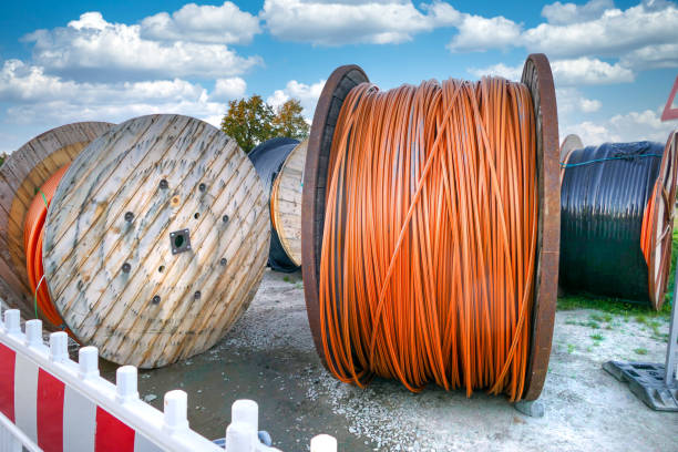
Environmental and Mechanical Installation Constraints
Installing medium voltage cables requires strict control over physical and environmental stressors to avoid damaging the insulation or shielding before the system even goes live.
- Temperature limits: Schedule laying operations at or above 0 °C. For urgent winter work, preheat cables to 20–30 °C and never bend them once they drop below freezing.
- Mechanical boundaries: Adhere strictly to the minimum bending radius and maximum pulling tension. Use anti-twist devices and calibrated winches during pulls to prevent screen or insulation damage.
- Routing strategy: Choose direct burial with at least 700 mm of cover for economical long runs. Use ducts and concrete trenches in areas requiring heavy mechanical protection and future accessibility.
- Thermal dissipation: Design trenches and crowded duct banks with adequate heat release. Apply ampacity derating for grouped circuits to keep the conductor operating temperature within the standard 90 °C limit.
Maintenance Accessibility and Long-Term Reliability
A smart cable layout does not just focus on getting the power flowing today. It anticipates routine inspections, unexpected troubleshooting, and facility upgrades over the next two to three decades.
- Component positioning: Place critical joints and terminations in dry, accessible, and mechanically protected areas like vaults, manholes, or indoor joint bays instead of burying them directly in the soil.
- Clearance and spacing: Maintain proper phase-to-phase spacing and phase-to-ground clearances inside switchgear and substations to ensure safe physical working space for personnel.
- Testing provisions: Incorporate test points and leave sufficient cable slack at terminations. Maintenance teams rely on this slack to easily disconnect, test for partial discharge or insulation resistance, and re-terminate the cables if necessary.
- Future expansion: Design layouts that leave physical space in trays, tunnels, and building entry paths. This allows you to add circuits or retrofit equipment later without triggering major civil excavation.
Balance Performance, Service Life, and Cost
Key Drivers of Performance
Conductor sizing and insulation selection directly determine the electrical performance of medium-voltage systems ranging from 1 kV to 50 kV. You should treat cable capacity as only the starting point, since real-world service life depends more on thermal loading, moisture exposure, and mechanical protection. In industrial environments, these factors continuously stress insulation systems and gradually reduce long-term reliability if not properly managed.
Service Life Management
To maintain predictable performance, asset managers rely on periodic condition monitoring to track insulation deterioration over time. By observing thermal behavior, environmental stress, and aging trends, you can plan replacements at the right stage of the cable lifecycle. This approach helps avoid both premature replacement costs and unexpected failures that could lead to unplanned downtime.
Life-Cycle Cost Optimization
The initial purchase price of a cable represents only a small portion of the total project cost. A more accurate evaluation comes from total cost of ownership, which includes installation labor, outage risk, and long-term maintenance frequency. You should align conductor size, fault-withstand capability, and jacket selection with actual system demands to ensure safety while avoiding unnecessary overspecification.
Frequently Asked Questions
How do you choose the correct insulation level for medium-voltage cables?
100% insulation is used in solidly grounded systems where faults clear quickly, while 133% and 173% insulation levels are designed for systems with delayed fault clearing or ungrounded conditions. The higher insulation levels provide additional protection against temporary overvoltages in demanding industrial environments.
What is the difference between XLPE and EPR insulation in industrial MV cables?
XLPE is widely used for its low dielectric losses and strong electrical performance in stable utility networks. EPR, however, offers better flexibility and superior resistance to moisture and chemical exposure, making it more suitable for harsh or contaminated industrial environments.
What is the minimum bending radius for medium-voltage cables?
Most shielded medium-voltage cables require a minimum bending radius of about 12 times the overall cable diameter, while armored designs may allow tighter bends depending on construction. Exceeding these limits can permanently damage insulation and shielding layers, reducing long-term reliability.
How does chemical exposure affect medium-voltage cable performance?
Chemical exposure can cause jacket materials to swell, crack, or lose flexibility over time, especially when exposed to oils or solvents. Once the outer sheath is compromised, moisture ingress can accelerate insulation degradation and significantly increase the risk of partial discharge failure.
What are the main causes of partial discharge in MV cable systems?
Partial discharge is usually caused by insulation defects, installation damage, or contamination such as moisture or air voids. If not controlled, it gradually erodes the insulation system and develops into electrical trees that eventually lead to complete cable failure in service.
Final Thoughts
Medium-voltage cable performance depends heavily on choosing the right insulation system, conductor material, and protective jacket for the actual operating environment. When you properly match insulation level, conductor design, and jacket materials to real environmental stresses, you significantly improve system reliability and extend service life while reducing total cost of ownership over time.
At Fil et câble LX, we help you move beyond guesswork by aligning cable configurations with your actual load conditions and site requirements. Our engineering-focused approach ensures that every solution is designed for performance, safety, and long-term stability in demanding applications.
Contact us today to review your project specifications and get a tailored technical recommendation for your next installation.




 French
  English
  Afrikaans
  Portuguese
  Hindi
Hindi  Italian
  Japanese
  Korean
  Spanish
  Arabic
  German
  Russian
  Swahili