






O que é extensão no cabo ADSS e por que isso é importante?
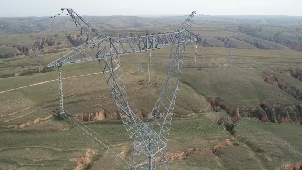
For ADSS (All-Dielectric Self-Supporting) cable, span is one of the most important parameters in overhead fiber optic cable design. It describes the distance between two adjacent support points, such as utility poles or transmission towers.
Span length affects much more than installation distance. It directly influences cable sag, mechanical tension, wind and ice loading, pole loading, clearance, and long-term cable reliability. A cable designed for a short span may not perform safely when installed over a much longer distance.
For this reason, ADSS cable selection should always consider the actual span and local installation conditions rather than relying only on the cable’s fiber count or nominal diameter.
What Is Span in ADSS Cable Design

Span is the single most critical factor in ADSS cable design. It dictates the cable’s strength, cost, and long-term reliability more than any other variable.
In an ADSS cable installation, span length is the horizontal distance between two consecutive attachment points.
For example, if an ADSS cable is installed between two utility poles that are 150 meters apart, the nominal span is 150 m. If the distance between the next two poles is 220 m, that section has a 220 m span.
When an ADSS cable manufacturer designs a cable for a specific application, engineers normally consider parameters such as:
| Parameter | Why It Matters |
|---|---|
| Span length | Determines the mechanical load on the cable |
| Cable weight | Influences sag and support-point tension |
| Wind load | Adds transverse mechanical loading |
| Ice load | Increases cable weight and tension in cold regions |
| Installation temperature | Changes cable tension and sag |
| Maximum operating temperature | Affects long-term sag performance |
| Cable construction | Determines tensile strength and mechanical limits |
| Installation condition | Influences the actual load on the cable |
Common Span Categories and Their Applications
ADSS cables are engineered for different span lengths based on the application environment. These are generally grouped into four main categories:
- Short Spans (50–100 m): These are typical for deployments in urban and suburban areas on distribution lines where poles are spaced closely together.
- Medium Spans (100–300 m): Commonly found along rural roads and in mixed-use corridors that carry both distribution and transmission lines.
- Long Spans (300–800 m): These are necessary for crossing wide valleys, rivers, or for installation on high-voltage transmission towers, which are spaced much farther apart.
- Extra-Long Spans (over 800 m): Reserved for major geographical challenges, these spans require custom-engineered cables and hardware to cross large rivers or navigate mountainous terrain.
How ADSS Cable Span Affects Mechanical Performance
ADSS cable span length is the primary factor driving decisions on tension, reliability, and hardware. Getting it wrong compromises the entire aerial plant’s integrity and lifespan.
Relationship Between Span, Tension, and Sag
The physics are straightforward. Increasing the distance between two poles directly increases the horizontal tension needed to support the cable’s weight. To keep this tension manageable, the cable must be allowed to sag more. This creates a critical trade-off, as too much sag can violate ground clearance requirements. Consequently, longer spans demand cables with a higher Rated Tensile Strength (RTS). Engineers use sag-tension charts to model these variables, ensuring the final installation meets clearance codes without over-stressing the cable under different wind and ice loads.
Impact on Long-Term Reliability and Failure Risk
Operating a cable near its maximum rated span is asking for trouble. Field studies are very clear on this: a staggering majority of ADSS cable failures happen on spans that exceed 90% of their rated length, especially in cold weather. This is why a non-negotiable design practice is to select a cable rated for a span that is at least 15% longer than the actual maximum span on your route. A longer unsupported length has greater exposure to dynamic loads from wind and ice, which accelerates material fatigue and significantly increases the probability of failure over time.
Vibration Susceptibility and Damping Needs
Longer spans act like giant guitar strings in the wind. They are far more susceptible to aeolian vibration—a high-frequency, low-amplitude oscillation that is a primary cause of fatigue damage, especially at the hardware clamp points. This is a serious issue for spans typically over 100 meters. For spans exceeding a threshold around 150 meters, vibration dampers become a mandatory accessory. Their purpose is to absorb and dissipate this harmful energy. The number of dampers needed, and their specific placement on the cable, are engineered based on the span length and line tension to be effective.
Influence on Installation Methods and Practices
You can’t install a long-span cable the same way you do a short one. While a basic pull might work for short distances, spans over 100 meters almost always require controlled tension stringing to prevent damage. During installation, the pulling tension must be carefully limited—usually to just 20-30% of the cable’s RTS—to avoid permanently straining the fibers or damaging the sheath. This level of control demands more sophisticated equipment, such as calibrated tensioners and pullers that can maintain a consistent force. Span length also dictates the strategic placement of splices to ensure each continuous run stays well within the cable’s mechanical limits.
Driving Cable Design and Hardware Selection
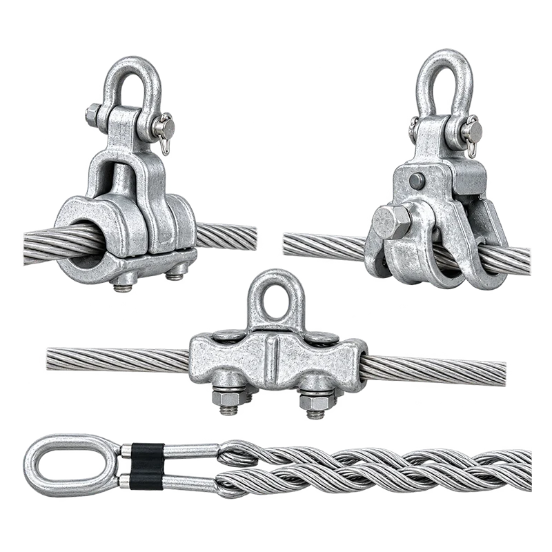
Maximum span is the first domino to fall in the entire design process. It is the primary factor that determines the required strength (RTS) of the ADSS cable itself. To achieve a higher RTS for longer spans, manufacturers add more aramid yarn reinforcement. This reinforcement results in a larger cable diameter and greater weight per meter. This increased weight and diameter, in turn, directly influence the final sag calculations and require larger, stronger pole hardware. All supporting hardware, from dead-ends to suspension clamps, must be selected to precisely match both the cable’s diameter and the increased mechanical loads of the intended span.
Your One-Stop Solution for Power Projects
Relationship Between Span, Sag and Installation Conditions
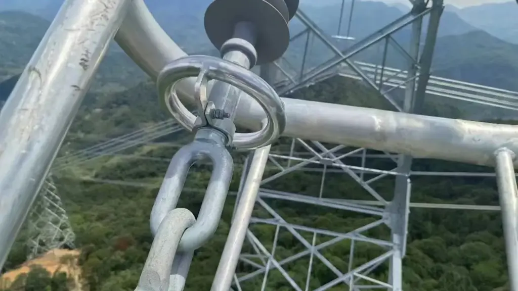
ADSS cable performance depends on a constant trade-off. Span, sag, and tension are physically linked and directly altered by weather, line design, and installation accuracy.
Fundamental Relationship Between Span, Sag, and Tension
In aerial cable design, the span is the horizontal distance between two poles, while sag is the vertical drop of the cable in the middle of that span. These two factors are intrinsically linked to the cable’s tension. For any given ADSS cable, the sag is approximately proportional to the square of the span length. If you double the distance between poles, the sag will increase by about four times, assuming tension remains constant.
Sag and tension share an inverse relationship. Pulling the cable tighter increases its tension and reduces the sag. Loosening the cable decreases tension and increases sag. This relationship is often estimated using the parabolic sag equation: Sag ≈ (wL²) / 8T, where ‘w’ is the cable’s weight per unit length, ‘L’ is the span, and ‘T’ is the horizontal tension. This formula provides a practical way to understand how these three variables interact.
Impact of Environmental Loading Conditions
Real-world conditions constantly alter a cable’s sag and tension. Temperature fluctuations cause the cable to expand in the heat and contract in the cold. Higher temperatures make the cable longer, which increases sag and reduces tension. Conversely, cold weather tightens the cable, increasing tension and reducing sag.
Wind adds a horizontal force, pushing the cable sideways and increasing its effective load. This added load raises the tension needed to support the cable. Ice accretion is often the most critical factor, especially in colder climates. Ice significantly increases the cable’s weight and diameter, which can dramatically increase sag and tension. Any robust design must account for the worst-case combinations of these loads, such as heavy ice buildup combined with high winds at low temperatures, to ensure the line’s structural integrity.
The Role of Ruling Span in Multi-Span Design
A typical fiber route consists of multiple spans of varying lengths, making it impractical to calculate and set the tension for each one individually. To solve this, engineers use the Ruling Span. This is a calculated, theoretical span length that represents the average tension behavior of an entire section of the line. It’s not a simple average; the calculation gives more weight to the longer spans, as they have the greatest impact on the line’s overall tension.
By setting the installation tension based on the Ruling Span, crews can use a single target to string the entire section. This ensures that all spans achieve an acceptable sag profile under different weather conditions. Longer spans will not sag too much, and shorter spans will not become over-tensioned.
Design Constraints: Clearance and Maximum Allowable Tension (MAT)
Every ADSS installation must operate within two primary constraints. First, the cable’s sag must be limited to maintain minimum ground clearance as required by safety codes. This ensures the cable remains a safe distance above roads, waterways, buildings, and other infrastructure. Second, the tension must never exceed the cable’s Maximum Allowable Tension (MAT), even under the most extreme weather conditions. Exceeding the MAT can damage the cable’s strength members and jeopardize its structural integrity.
A critical subset of this tension limit is the strain on the optical fibers themselves. Fiber strain must typically be kept below a very small percentage (por exemplo, 0.3% elongation) to prevent signal degradation or breakage. The final design is a balance between span length, sag, and tension to satisfy both clearance requirements and the cable’s strength limitations.
Influence of Installation Practices
The final, in-service sag and tension of a cable are directly set by the conditions at the time of installation. The ambient temperature during stringing is particularly important. Field crews use sag-tension charts that are specific to the cable model and ruling span, making adjustments for the temperature on the day of the install. Getting this wrong can have significant consequences.
If a cable is sagged incorrectly, it can lead to clearance violations during hot summer weather or create excessive tension that damages the cable during cold winter weather. The initial tension calculations must also account for long-term creep, which is the permanent, slow elongation of the cable’s strength members over many years. This ensures the cable maintains safe clearances throughout its service life.
Factors That Influence Maximum ADSS Cable Span
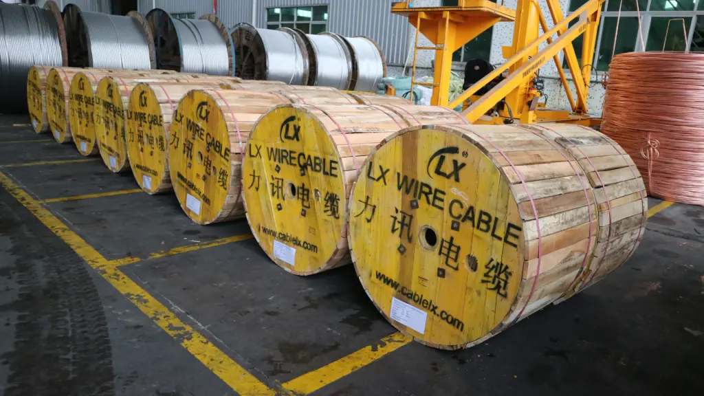
There is no single maximum span that applies to every ADSS cable. The achievable span depends on the cable design and the environmental conditions of the project.
1. Cable weight and diameter
A heavier cable creates a greater distributed load. Cable diameter also affects wind loading because a larger cable presents a larger surface area to the wind.
2. Wind loading
Strong wind creates lateral pressure on the cable and increases the overall mechanical load. Areas exposed to high wind require a more conservative mechanical design.
3. Ice loading
In cold regions, ice can accumulate around the cable. This can significantly increase the effective cable weight.
A cable that performs well in a warm, low-wind environment may require a different design for an area with heavy ice and strong winds.
4. Installation temperature
Installation tension must be selected according to the expected temperature conditions. Incorrect tension during installation can lead to excessive stress or excessive sag later.
5. Support structure
The strength and condition of utility poles or towers also matter. A cable may have sufficient tensile capacity for a long span, but the supporting structure may not be designed for the additional load.
6. Required safety factor
ADSS cable systems are normally designed with appropriate safety margins. The required factor depends on the applicable standards, condições ambientais, and project specifications.
7. Cable construction
The number and arrangement of strength members, sheath structure, cable diameter, and overall cable design all influence mechanical performance.
This is why engineers should not select an ADSS cable based only on “maximum span” shown on a general product sheet. The actual span should be evaluated together with the project’s environmental and installation conditions.
How to Select the Right ADSS Span for Different Applications
| Aplicativo | Span Length | Voltage Level | Cable Structure | Jacket Type | Design Focus | Typical Diameter |
|---|---|---|---|---|---|---|
| Distribution Lines | 50–300 m | Typically <35 kV | Central tube for ≤150 m; Layered-twist for ≤300 m | PE (Polyethylene) is often sufficient in low-pollution areas. | Confirming pole strength for added load and maintaining ground clearance under max sag. | ~11–12 mm |
| Transmission Lines | 300–800 m | 35 kV to 220 kV | High-RTS Layered-twist design with robust aramid reinforcement. | AT (Anti-Tracking) jacket is recommended, especially above 35 kV or in polluted areas. | Detailed sag-tension analysis for wind/ice loads and use of vibration dampers. | ~14 mm |
| EHV Lines & River Crossings | 800 m+ | 220 kV, 500 kV, and above | High-RTS, reinforced layered design compliant with IEEE 1222 standards. | Double-jacket AT (Anti-Tracking) is required for high electric fields. | Precise sag-tension modeling (por exemplo, PLS-CADD), 15%+ span safety margin, and robust hardware. Used for river crossings and corridors with widely spaced EHV towers. | (Varies) |
| Telecom-Only Aerial Routes | Up to 300 m | N/A (unenergized poles) | Lightweight central tube for ≤100 m; standard layered-twist for ≤300 m. | PE (Polyethylene) is the standard choice. | Purely mechanical considerations, including RTS to handle environmental loads like wind and ice. Used on dedicated fiber routes where no power lines are present. | (Varies) |
Professional ADSS Cable Solutions for Different Project Requirements
LX Electrical provides customized ADSS cable solutions for utility, telecom, e projetos de infraestrutura, helping customers match cable construction to actual route conditions.
Key advantages include:
- Project-based cable selection based on span and environmental requirements
- Customized mechanical design for different installation conditions
- Consistent manufacturing quality for bulk and long-term projects
- One-stop cable supply from specification confirmation to production and delivery
- Technical coordination to help reduce cable selection and installation risks
Planning an ADSS project? Send LX Electrical your fiber count, maximum span, temperature range, wind or ice conditions, and installation requirements. Our team can help you identify a suitable ADSS cable specification for your project.
Perguntas frequentes
What is span length in ADSS cable design?
Span length is the horizontal distance an ADSS cable can bridge between two support structures, such as poles or towers, without intermediate support. It is a critical design parameter that directly determines the cable’s required strength, its sag and tension characteristics, and the type of hardware needed for a safe installation.
How does span affect ADSS tension and sag?
Span length has a significant, non-linear impact. For a given sag, doubling the span quadruples the required tension. Da mesma maneira, for a given tension, sag increases with the square of the span. This means longer spans sag much more and require substantially stronger cables or higher installation tensions to maintain safe clearances.
What is a typical span between utility poles?
In urban or suburban areas, a typical span between distribution utility poles is around 35–40 meters (about 115–130 feet). In more open, rural settings, this distance often increases to a range of 70–90 meters (about 230–300 feet). The exact spacing depends on the power line voltage, terrain, and local standards.
How do wind and ice loads influence span decisions?
Wind and ice add significant mechanical load to the cable, which increases both sag and tension. Engineers must use local climate data to calculate these worst-case loads. A span that is perfectly safe in calm weather may sag into a hazardous position or experience tension beyond its limits during a storm, so span decisions are always governed by these environmental factors.
What happens if a span is miscalculated?
A miscalculation can lead to serious failures. If a span is longer than the cable was designed for, it can become over-tensioned, leading to permanent fiber damage, attenuation, or even breakage. If loads are underestimated, the cable can sag excessively, violating mandatory safety clearances over roads or creating electrical hazards near power lines.
Why do engineers request span data before ADSS design?
Engineers need span data before starting a design because it is the most important factor influencing the mechanical and structural requirements of the entire system. The maximum span on a route dictates the cable’s necessary strength, its sag under load, required safety clearances, and the selection of all supporting hardware. Without it, a safe and reliable design is not possible.


