





O guia BOM completo para juntas de cabos termorretráteis & Rescisões
Ao comprar juntas e terminações de cabos termorretráteis para um projeto de cabo de alimentação, o kit em si é apenas parte da decisão. O verdadeiro desafio é garantir que cada componente corresponda à construção do cabo, nível de tensão, tamanho do condutor, ambiente de instalação, e desempenho elétrico necessário.
Um completo Lista de materiais (BOM) ajuda os compradores a evitar a falta de componentes, dimensões incorretas, materiais incompatíveis, e custos de aquisição desnecessários.
Este guia explica o que normalmente é incluído nos kits de junção e terminação de cabos termorretráteis, quais especificações técnicas são importantes, como selecionar o kit certo, e como um fornecedor de cabos completo pode simplificar a aquisição para grandes projetos de energia.
O que são juntas e terminações termorretráteis de cabos
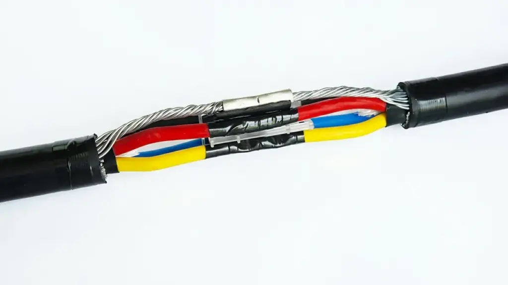
As juntas e terminações de cabos termorretráteis são acessórios de cabos usados para conectar, selo, isolar, e proteger os cabos de alimentação.
UM junta de cabo termorretrátil conecta duas seções de cabo enquanto restaura o isolamento elétrico, blindagem, proteção mecânica, e resistência à umidade ao redor do ponto de conexão. É comumente usado para redes de distribuição subterrâneas, sistemas de energia industriais, projetos de utilidade, e instalações de energia renovável.
UM terminação do cabo termorretrátil, por outro lado, prepara a extremidade de um cabo para conexão a equipamentos como transformadores, comutador, painéis de distribuição, motores, e linhas aéreas.
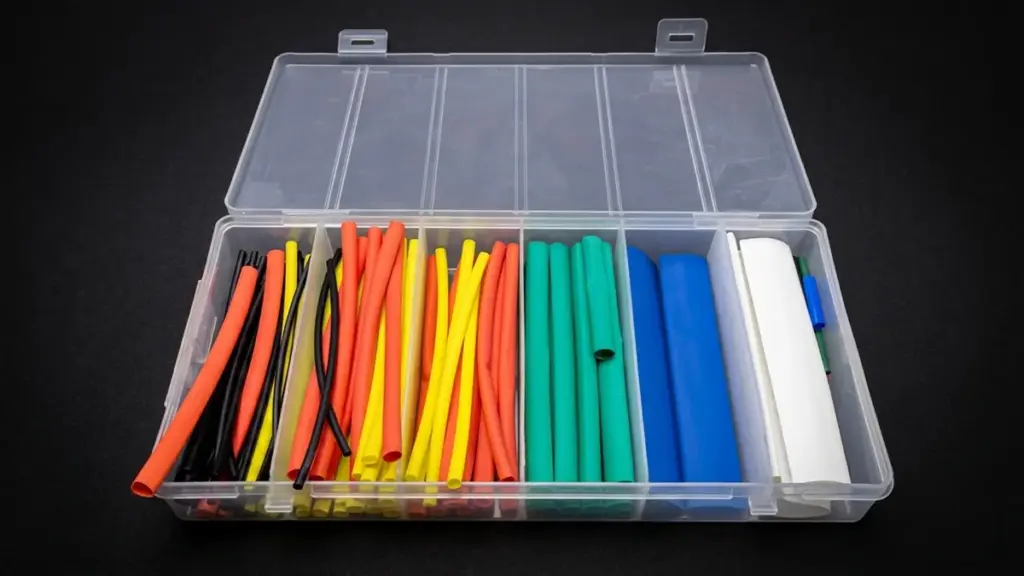
O princípio básico é simples: tubos poliméricos especialmente projetados são aquecidos durante a instalação. Eles encolhem firmemente ao redor do cabo e criam camadas controladas de isolamento e vedação.
Lista completa de BOM para kits de juntas de cabos termorretráteis
Um kit típico de junta termorretrátil contém várias camadas funcionais. A lista técnica exata muda de acordo com a tensão do cabo, seção transversal do condutor, tipo de isolamento, número de núcleos, construção de tela, e ambiente de instalação.
| Componente BOM | Função principal & Descrição Técnica | Quantidade / Unidade |
|---|---|---|
| Conector condutor / Virola | Une condutores usando conexão mecânica de crimpagem ou parafuso de cisalhamento para garantir a continuidade elétrica. | 1 computador/fase |
| Tubos de controle de estresse | Controla e suaviza o gradiente do campo elétrico em ambos os lados dos cortes da blindagem do cabo. | 2 peças/fase |
| Mástique de Estresse / Mástique de preenchimento amarelo | Preenche lacunas de ar e rebaixamentos no conector e cortes na tela de isolamento para evitar descarga parcial. | Conforme necessário |
| Parede Dupla / Manga isolante de camada dupla | Combina tubo isolante primário e camada externa semicondutora para restaurar o isolamento primário e proteger a junta. | 1 computador/fase |
| Malha de arame de cobre / Malha de blindagem | Envolve o isolamento da junta para restaurar a blindagem metálica contínua e o caminho de aterramento entre as seções do cabo. | 1 rolar / definir |
| Trança de Terra ou Fio de Aterramento | Restaura um caminho de aterramento confiável através da junta. | 1 definir |
| Componentes de ligação de armadura | Conecta a blindagem do cabo através da junta quando necessário, usando molas de força constante ou anéis de suporte. | 1 definir |
| Mastique de Isolamento / Tira de vedação | Preenche superfícies irregulares e suporta isolamento elétrico e vedação ambiental. | Conforme necessário |
| Manga externa de revestimento de parede pesada | Espesso, tubo termorretrátil externo revestido com adesivo proporcionando resistência mecânica, selo de umidade, e proteção contra impactos. | 1 computador |
| 3-Bota de dedo (3-Somente núcleo) | Sela e protege a área entrepernas onde um cabo de 3 núcleos se divide em fases individuais. | 2 peças |
| Pano Abrasivo & Kit de limpeza | Usado para preparação de superfície de cabos, desengordurante, e limpar o isolamento antes da termorretrátil. | 1 conjunto |
Observação: As quantidades padrão mostradas acima são baseadas em uma configuração típica de kit de cabo de 3 núcleos. Os itens e quantidades reais da BOM podem variar dependendo da especificação do cabo (1-núcleo versus. 3-essencial), classificação de tensão (influenciando o número necessário de chuvas), e opções de conector/terminal (crimpagem vs.. parafuso de cisalhamento). Consulte a folha de dados específica do fabricante para obter o conteúdo preciso do kit.
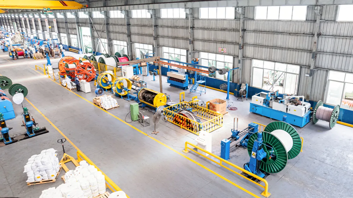
Seu parceiro chave na mão para projetos de energia.
Lista completa de BOM para kits de terminação de cabos termorretráteis
Um kit de terminação usa um princípio semelhante, mas tem um arranjo físico diferente porque o cabo está sendo conectado a um equipamento externo e não a outro cabo.
Uma BOM típica de terminação termorretrátil de média tensão pode incluir:
| Componente BOM | Aplicabilidade | Função principal & Descrição Técnica | Quantidade / Unidade |
|---|---|---|---|
| Terminais de cabo (Crimpagem ou parafuso de cisalhamento) | Interior & Ar livre | Conecta condutores de cabos a barramentos, comutador, transformadores, ou linhas aéreas. | 1 computador/fase |
| Tubo termorretrátil anti-rastreamento | Interior & Ar livre | Alto desempenho, sem rastreamento, Tubo resistente a UV que protege o isolamento do núcleo contra rastreamento elétrico e intempéries. | 1 computador/fase |
| Tubos de controle de estresse | Interior & Ar livre | Alivia a concentração do campo elétrico na extremidade cortada da camada de blindagem semicondutora do cabo. | 1 computador/fase |
| Mástique para alívio de estresse / Mástique Amarelo | Interior & Ar livre | Aplicado sobre a borda de corte do semicondutor para preencher vazios e otimizar a distribuição de tensão elétrica. | Conforme necessário |
| Galpões de chuva / Extensores de Crescimento | Somente ao ar livre | Aumenta a distância de fuga da superfície para resistir à chuva, poluição, e condições atmosféricas severas. | 1–3 peças/fase |
| Mástique de vedação de talão / Mástique Vermelho | Interior & Ar livre | Veda a lacuna entre a palma/cano do terminal do cabo e o tubo termorretrátil para evitar a entrada de umidade. | Conforme necessário |
| Mangas de identificação de cores de fase | Interior & Ar livre | Vermelho curto, amarelo, e tubos termorretráteis azuis/verdes para identificar a sequência de fases (L1, L2, L3). | 1 definir |
| 3-Bota de dedo | 3-Somente núcleo | Bota termorretrátil que sela a área da virilha onde os três núcleos se separam em núcleos únicos. | 1 computador |
| Condutor / Mangas de proteção central | 3-Somente núcleo | Cobre cada núcleo desde a inicialização do breakout até o ponto de terminação para triagem/proteção adicional. | 3 peças |
| Trança da Terra & Molas de Força Constante | Interior & Ar livre | Fornece conexão de aterramento sem solda da fita de cobre/blindagem do fio e armadura ao sistema de aterramento. | 1 definir |
| Limpeza & Acessórios de instalação | Interior & Ar livre | Inclui solventes desengordurantes, fita abrasiva, Fita de PVC, luva, e manual de instruções de montagem. | 1 conjunto |
Observação: As quantidades padrão mostradas acima são baseadas em uma configuração típica de kit de cabo de 3 núcleos. Os itens e quantidades reais da BOM podem variar dependendo da especificação do cabo (1-núcleo versus. 3-essencial), classificação de tensão (influenciando o número necessário de chuvas), e opções de conector/terminal (crimpagem vs.. parafuso de cisalhamento). Consulte a folha de dados específica do fabricante para obter o conteúdo preciso do kit.
Materiais e especificações técnicas que você deve conhecer
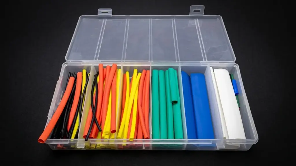
Os materiais comuns incluem poliolefina reticulada, borracha de silicone, EPDM, materiais semicondutores, cobre, alumínio, e mastiques de vedação. Cada material tem uma função diferente.
Componentes principais poliméricos e metálicos
A base de qualquer junta de cabo termorretrátil é um sistema de materiais projetados. O corpo principal consiste em tubos poliméricos para isolamento e vedação, que funciona em conjunto com componentes metálicos que fornecem a conexão elétrica. Cada parte é selecionada para replicar o desempenho do cabo original.
- Materiais Poliméricos: O corpo principal da junta utiliza poliolefina reticulada ou EPDM, projetado especificamente para fornecer isolamento robusto e uma vedação ambiental hermética quando o calor é aplicado.
- Conectores Metálicos: Terminais de compressão de alumínio ou cobre criam a ligação elétrica e mecânica entre os condutores. Estes devem estar em conformidade com padrões como IEC 61238-1 para garantir uma conexão estável.
- Continuidade de tela e armadura: Os kits contêm tranças de cobre, malhas, e molas de força constante. Esses componentes reconectam a blindagem metálica do cabo, garantindo um caminho de terra contínuo e seguro.
- Compatibilidade de materiais: Todos os componentes são escolhidos para corresponder às características do próprio cabo, como o 90 Classificação térmica contínua em °C necessária para cabos com isolamento XLPE.
Projeto de isolamento elétrico e controle de tensão
Para média tensão (VM) articulações, simplesmente reconstruir o isolamento não é suficiente. Gerenciar os campos elétricos intensos em pontos onde a blindagem do cabo é cortada é fundamental para evitar falhas a longo prazo. Um aplicativo sem lacunas é o objetivo principal.
- Sistema de controle de estresse: Em aplicações de MT, tubos especiais e mastiques com alta permissividade (εr ≥ 15) são usados para gerenciar e suavizar a tensão do campo elétrico onde a tela termina.
- Reconstrução de Isolamento: A junta restaura a espessura original do isolamento do cabo. Isto é feito aplicando múltiplas camadas de tubo termorretrátil ou uma única, corpo elastomérico pré-moldado.
- Aplicativo sem anulação: Mastiques de vedação são cruciais para preencher quaisquer lacunas de ar ao redor do conector e etapas de isolamento. A eliminação de vazios evita descargas parciais, uma causa primária de falha articular.
- Classe de tensão: Todo o sistema de isolamento é projetado e testado para suportar os testes de tensão CA e de impulso especificados para sua classe de tensão designada., como 11 kV ou 33 kV.
Vedação Ambiental e Proteção Mecânica
Uma articulação deve sobreviver ao seu ambiente, seja enterrado no solo ou exposto ao clima. Esta proteção vem de uma defesa multicamadas contra a entrada de umidade e danos físicos, garantindo que a conexão permaneça isolada e intacta durante toda a sua vida útil.
- Barreira Primária de Umidade: Um revestimento adesivo termofusível dentro da manga externa de parede espessa é ativado com o calor. Ele flui para preencher irregularidades da superfície e cria uma durabilidade, ligação estanque com a bainha do cabo.
- Preenchimento de vazios: Fitas mastique são aplicadas para selar formas irregulares, como aqueles em torno de fios ou conectores de armadura, fornecendo uma defesa secundária crítica contra a umidade.
- Bloqueio Longitudinal de Água: Alguns kits incluem fitas especiais que incham com água que se expandem em contato com a umidade. Eles são projetados para impedir que a água se desloque ao longo do núcleo do cabo se a bainha externa estiver danificada em outro lugar.
- Durabilidade Mecânica: Um pesado, manga externa de parede espessa oferece alta resistência à abrasão e impactos, protegendo a junta durante o enterramento direto e do movimento do solo ou outras tensões mecânicas.
Principais classificações e parâmetros técnicos
Ao revisar uma BOM, os compradores devem prestar atenção a estas especificações:
- Tensão nominal e tensão máxima do sistema
- Seção transversal do condutor do cabo
- Material condutor
- Número de núcleos
- Material de isolamento de cabo
- Diâmetro de isolamento
- Construção de tela metálica
- Diâmetro externo do cabo
- Taxa de encolhimento
- Dimensões recuperadas e expandidas
- Temperatura operacional
- Requisitos de resistência a curto-circuito
- Instalação interna ou externa
- Resistência aos raios UV e às intempéries
- Padrões de teste exigidos
Para acessórios de média tensão, o projeto elétrico deve ser considerado como um sistema completo e não como uma coleção de tubos e conectores independentes. CEI 60502-4:2023 cobre requisitos de teste de tipo para acessórios relevantes, com métodos de teste referenciados na IEC 61442.
Para projetos acima 30 kV, CEI 60840 fornece métodos de teste e requisitos para cabos e acessórios até 150 kV, portanto, o padrão aplicável deve ser confirmado antes da aquisição.
Padrões Governantes e Conformidade
As juntas de cabos operam sob uma estrutura rigorosa de padrões industriais que determinam o desempenho, qualidade dos materiais, e segurança. Conformidade não é opcional; é uma medida direta da confiabilidade e adequação de um produto para uso em redes de energia críticas.
- Padrões de desempenho conjuntos: Os kits completos são testados de acordo com padrões como ENA 09-13 ou É 13573. Estas normas sujeitam a junta a uma sequência rigorosa de, térmico, e tensões mecânicas.
- Conformidade do conector: Os terminais condutores dentro do kit devem atender aos requisitos da IEC 61238-1, que cobre sua estabilidade elétrica e resistência mecânica a longo prazo após a instalação.
- Qualidade dos Materiais: Os materiais poliméricos básicos geralmente seguem padrões como UL 224, que define critérios de inflamabilidade e classificações básicas de isolamento, garantindo propriedades materiais consistentes e seguras.
- Regulamentos Ambientais: As especificações modernas frequentemente exigem que os materiais sejam livres de halogênio. Isto está em conformidade com diretivas como RoHS e melhora o desempenho da segurança contra incêndio, reduzindo a emissão de fumaça tóxica.
Como selecionar o kit termorretrátil correto para projetos de cabos de alimentação
A escolha do kit termorretrátil correto para projetos de cabos de alimentação requer a correspondência das especificações do kit com o cabo, tensão, e meio ambiente. Uma incompatibilidade é um ponto de falha comum e caro.
Fazer essa seleção certa desde o início evita retrabalho e garante confiabilidade a longo prazo. O processo é simples se você for sistemático. Ele se divide em cinco etapas principais, desde a definição das necessidades do seu projeto até a verificação do conteúdo final do kit em relação à sua lista de materiais (BOM).
| Critérios de seleção | Principais considerações |
|---|---|
| Defina os principais parâmetros do projeto |
|
| Avalie os principais critérios técnicos e materiais |
|
| Execute dimensionamento e medição precisos |
|
| Combine o kit com a aplicação específica |
|
| Verifique o conteúdo do kit e o alinhamento da BOM |
|
Em última análise, um projeto de cabo de alimentação bem-sucedido depende de acertar esses detalhes durante a aquisição. A melhor técnica de instalação não salva um kit que não combinava desde o início. Um processo de seleção disciplinado garante que o que chega ao local é exatamente o que é necessário para realizar o trabalho corretamente.
Erros comuns ao comprar juntas e terminações de cabos
Muitas falhas nas juntas dos cabos começam na aquisição. Erros comuns incluem perseguir preços baixos, especificando kits incompletos, e ignorando a instalação do mundo real e as demandas ambientais.
Escolhendo kits sem validação técnica completa
O erro mais comum é selecionar juntas ou terminações de cabos com base no preço baixo e não no alinhamento técnico. Um produto simplesmente marcado “11 kV” não é bom o suficiente. Você deve validar sua compatibilidade com a ficha técnica de construção do cabo específico. Isso significa confirmar que funciona com o tipo exato de isolamento (como XLPE, RPE, ou PILC) e tipo de tela (gravado ou fio). Ignorando os relatórios de teste de tipo do fabricante – que verificam o desempenho para descarga parcial, tensão suportável, e ciclagem térmica – é um caminho direto para falha prematura.
Especificação de kits incompletos ou de componentes mistos
Comprando terminais de um fornecedor, tubos de controle de estresse de outro, e selar componentes de um terceiro é uma receita para o desastre. Um kit de junção de cabos é um sistema integrado que foi projetado e testado para funcionar em conjunto. A mistura de componentes de diferentes fabricantes quebra a integridade do projeto e anula a aprovação do teste de tipo. Também é fácil omitir acessórios essenciais como mástiques, solventes de limpeza, ou materiais específicos de controle de tensão da lista de materiais. Sempre verifique a lista de conteúdo de um kit com os requisitos do projeto, em vez de presumir que ele inclui tudo o que é necessário.
Subestimando as demandas ambientais e mecânicas
Compra de uma junta com classificação interna para uma área externa, submerso, ou instalação diretamente enterrada levará à entrada de umidade e falha. É um erro fundamental. Você deve especificar kits com a correta proteção ambiental. Para aplicações externas, isso significa exigir bainhas externas resistentes a UV. Para instalações industriais, significa materiais quimicamente resistentes. Também é crucial lembrar a proteção mecânica, como kits de continuidade de armadura ou braçadeiras de alívio de tensão. Finalmente, ignorar as restrições de espaço de instalação pode forçar os instaladores a violar o raio mínimo de curvatura do cabo, causando danos imediatos ou latentes.
Ignorando os requisitos de instalação e teste
A aquisição não envolve apenas comprar o kit em si. Trata-se de permitir uma instalação bem-sucedida. Isso significa também adquirir as ferramentas especializadas necessárias para o trabalho, como ferramentas de remoção de tela semicondutoras e ferramentas de chanframento. É um erro presumir que as equipes de instalação têm acesso ao treinamento do fabricante ou a manuais detalhados – estes devem fazer parte do pacote de aquisição. Da mesma maneira, o plano de inicialização do projeto deve incluir equipamentos de teste essenciais, como testadores de resistência de isolamento, e suprimentos necessários para controle de contaminação, como solventes aprovados e lenços sem fiapos para preparação de superfícies.
Como um fornecedor completo simplifica a aquisição de acessórios para cabos
Para grandes projetos de cabos de energia, comprar cabos e acessórios de vários fornecedores pode criar um trabalho de coordenação desnecessário.
O comprador pode precisar gerenciar cotações separadas para cabos, articulações, rescisões, conectores, componentes de aterramento, ferramentas para puxar cabos, acessórios, e outros materiais elétricos. Diferentes fornecedores também podem usar diferentes especificações e sistemas de embalagem.
UM fornecedor completo de transmissão de energia pode simplificar esse processo consolidando produtos em um plano de aquisição.
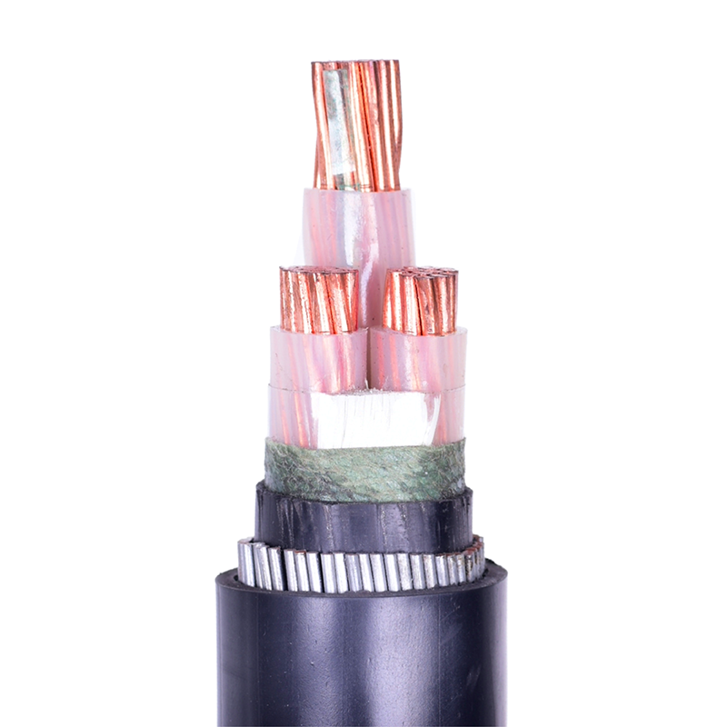
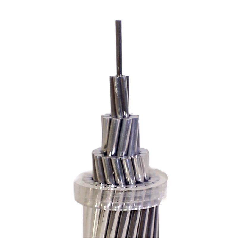
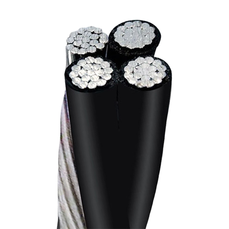
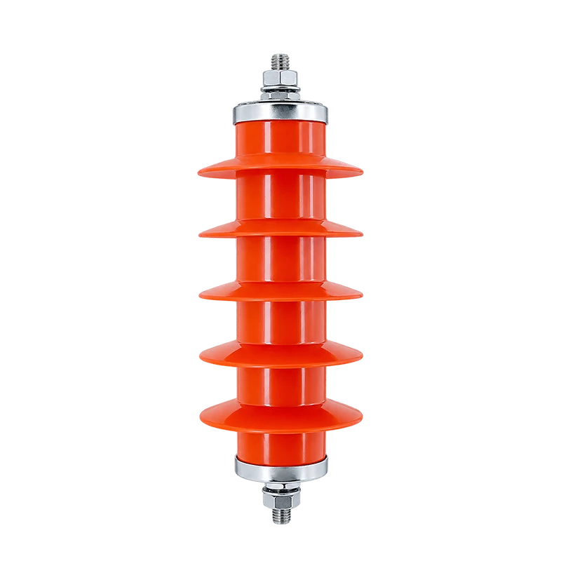
CABO LX fornece cabos de alimentação juntamente com acessórios de cabos e outros produtos de transmissão de energia, apoiando os clientes com uma abordagem de aquisição de fonte única. A sua gama de produtos abrange cabos de alimentação, cabos solares, condutores aéreos, cabos elétricos, acessórios de energia, isoladores, ferramentas, e outros acessórios.
Para um projeto envolvendo juntas e terminações termorretráteis, esta abordagem pode ajudar os compradores:
- Consolide várias categorias de produtos em uma cotação
- Combine os acessórios do cabo com as especificações do cabo fornecidas
- Reduza a comunicação entre vários fornecedores
- Coordene a produção e a entrega com mais eficiência
- Reduza o risco de falta de componentes acessórios
- Simplifique a documentação e inspeção de qualidade
- Construir uma relação de fornecimento mais consistente a longo prazo
A LX CABLE afirma que atende clientes em mais de 130 países e oferece soluções completas de aquisição e consolidação para cabos e acessórios elétricos e de telecomunicações.
Se você está planejando um projeto de cabo de alimentação e precisa de cabos, juntas termorretráteis, rescisões, acessórios, ou acessórios relacionados, entre em contato com a LX CABLE para obter uma cotação coordenada e uma solução de fornecimento completa. Compartilhe as especificações do seu cabo, nível de tensão, ambiente de instalação, quantidades necessárias, e destino de entrega para receber uma recomendação de produto mais adequada.
Perguntas frequentes
O que é uma junta de cabo termorretrátil?
Uma junta de cabo termorretrátil é um sistema de conexão que utiliza um elemento ativado por calor, manga encolhível para isolar, selo, e proteger mecanicamente uma emenda de cabo. Combina uma junta condutora, como um conector de crimpagem ou parafuso, com a camada encolhível para garantir a continuidade elétrica, vedação ambiental, e proteção mecânica para a conexão.
Quais componentes estão incluídos em um kit de junta típico?
Um kit típico de junta termorretrátil contém um conector de condutor, tubos de isolamento termorretrátil, materiais de controle de tensão para média tensão, mastiques de vedação ou revestimentos adesivos, e peças para continuidade de tela ou terra, como malha de cobre. Os kits para cabos blindados também incluem componentes para restauração da blindagem, como anéis de suporte e braçadeiras.
Como funcionam os tubos de controle de tensão em média tensão (VM) articulações?
Em juntas MT, tubos de controle de tensão são componentes essenciais para classificação em campo. Feito de alta permissividade (Oi-K) e materiais de resistividade controlada, eles redistribuem o campo elétrico em pontos agudos, como cortes de blindagem e conectores. Isso evita altas concentrações de tensão elétrica, o que poderia levar a descarga parcial e quebra de isolamento, garantindo a confiabilidade da junta a longo prazo.
As juntas termorretráteis são adequadas para uso externo??
Sim, juntas termorretráteis são adequadas para uso externo, desde que o kit específico seja projetado e classificado para isso. Os principais recursos para desempenho externo incluem materiais resistentes a UV (poliolefina tipicamente preta), revestido com adesivo (parede dupla) tubulação para impermeabilização eficaz, e espessura de parede apropriada para durabilidade mecânica.
Quais padrões geralmente se aplicam aos kits de junção de cabos?
Os kits de juntas de cabos são regidos por vários padrões, incluindo IEC 60502-4 para acessórios de média tensão, EM 50393 para juntas de baixa tensão, e VDE 0278. Os conectores dentro dos kits normalmente estão em conformidade com IEC 61238-1. Esses padrões garantem que o produto atenda ao desempenho crítico, segurança, e requisitos de teste de tipo.
Quais ferramentas são necessárias para instalar juntas termorretráteis?
Installing a heat shrink joint requires cable preparation tools (cutters, strippers), connector installation tools (crimpers), a reliable heat source like a heat gun or propane torch, and cleaning supplies such as manufacturer-approved solvents and lint-free cloths. Personal protective equipment (PPE) is also essential.
What mistakes commonly cause cable joint failures in the field?
Most cable joint failures result from installation errors. Common mistakes include poor cable preparation like nicks or contamination, incorrect crimping leading to overheating, inadequate moisture sealing, and improper heat application that leaves voids. Using the wrong kit for the cable type or voltage rating is another frequent cause of failure.


