











RTS vs MAT vs EDS: Understanding ADSS Mechanical Parameters
Every ADSS cable you put on a utility pole carries tension 24 hours a day, 365 days a year — its own weight pulling down, wind pushing sideways, ice adding load without warning. Engineers and procurement teams evaluating ADSS cable for overhead fiber projects routinely receive datasheets listing three tensile ratings: estrategia en tiempo real, MAT and EDS. Getting these numbers wrong means you either overspend on a cable stronger than needed, or you underspec and watch the fiber accumulate attenuation within months.
This guide breaks down what each parameter actually means, how they relate mathematically (MAT ≈ 40 % estrategia en tiempo real, EDS ≈ 16–25 % estrategia en tiempo real), and how to use them as a buyer to match cable to span, loading conditions, and project lifetime.
Key Takeaways
- estrategia en tiempo real (Resistencia a la tracción nominal) is the cable’s calculated breaking force; actual breaking must be ≥ 95 % of RTS per IEEE Std 1222.
- MAT (Maximum Allowable Tension) ≈ 40 % of RTS — the maximum combined weather load where fiber shows zero permanent strain.
- EDS (Everyday Sag Tension) = 16–25 % of RTS — the long-term average under no wind, no ice, annual mean temperature.
- Fiber strain at MAT must stay ≤ 0.1 % (central tube) or ≤ 0.05 % (layered) with no additional attenuation.
- Always cross-check a supplier’s MAT/EDS against your site’s span, sag, and worst-case wind/ice loading before you place an order.
- ADSS ratings are governed by IEEE Std 1222-2019 (América del norte) y CEI 60794-4-20 (international).
Why ADSS Tensile Ratings Decide Cable Safety
Unlike metallic conductors, ADSS cable is entirely dielectric — no steel messenger, no ground wire. The aramid (or glassFRP) strength members inside the jacket are the only load-bearing element holding the cable between poles. If those members yield, the cable drops. If tension exceeds fiber strain limits, signal attenuates permanently.
Utility project owners specify three distinct tension thresholds to address three distinct scenarios: manufacturing quality (estrategia en tiempo real), extreme weather survival (MAT), and day-to-day optical stability (EDS). Each serves a different engineering purpose. Confusing them leads to either overbuilt, expensive cable or underbuilt cable that fails in the first ice storm.
What Is Rated Tensile Strength (estrategia en tiempo real) in ADSS Cable
RTS — also called UTS (Ultimate Tensile Strength) or Rated Breaking Load — is the calculated sum of tensile strengths of all load-bearing members (aramid yarn, FRP rods) in the cable cross-section. It is not the measured break force from one sample; it is a design value derived from component specs and construction geometry.
Estándar IEEE 1222-2019 requires that the actual measured breaking force in a production test must be at least 95 % of the computed RTS. If it drops below that threshold, the cable fails acceptance.
For typical medium-span ADSS (12–48 fiber), RTS ranges roughly 6–40 kN, depending on diameter and aramid content. Larger counts or long-span variants (144–288 fiber) can exceed 60 kN.
Buyer check: ask the factory for the RTS test report showing actual breaking force / calculated RTS ratio. Any value below 95 % means the cable is out of spec. Do not accept a datasheet that lists RTS but cannot supply the test record.
What Is Maximum Allowable Tension (MAT)
MAT is the highest tension the cable should experience under worst-case combined loads: maximum design wind speed (often 160 km/h gust), full radial ice thickness, and minimum design temperature. At MAT the fiber must still be strain-free — no permanent elongation, no added attenuation beyond initial values.
Typical design ratio: MAT ≈ 40 % of RTS (some long-span designs push to 45 %). This safety margin protects against short-term overload during storms and also limits creep on the aramid over decades.
Fiber strain limit at MAT: ≤ 0.1 % (central-tube ADSS) or ≤ 0.05 % (layered/stranded). These are the thresholds set by IEC 60794-4-20 for zero residual attenuation.
MAT is your sag-tension-span calculation anchor. Given the site wind zone, ice thickness, and annual minimum temperature, your line engineer computes the operating tension and checks it stays below MAT. If the span exceeds what MAT allows, you need a higher-RTS cable — which means a thicker diameter and heavier aramid.
What Is Everyday Sag Tension (EDS)
EDS — sometimes labeled EST (Everyday Sag Tension) o “annual average operating tension” — represents the steady-state load the cable carries on a typical calm day: no wind, no ice, annual mean temperature (usually 15–20 °C for most locations). At EDS the cable is in its “home” position on the span, and the fiber has zero strain and zero extra loss.
Typical ratio: EDS = 16–25 % of RTS (industry practice settles around 18–22 %).
EDS governs two long-term concerns:
- Fatigue and aeolian vibration — the cable will oscillate in light wind millions of times over its service life. EDS sets the baseline stress; if it is too high, the aramid and the fiber accumulate micro-damage.
- Annual creep — aramid creeps under sustained load. A lower EDS means less permanent elongation per year, which preserves sag and fiber margin.
Anti-vibration armor rods or helical dampers are designed around EDS. If you change EDS, you must re-evaluate the vibration protection scheme.
RTS vs MAT vs EDS Compared for Buyers
The following table summarizes the three parameters, their engineering roles, and the standard ratios that link them.
| Parameter | Abbrev. | Typical % of RTS | Engineering Role |
|---|---|---|---|
| Resistencia a la tracción nominal | estrategia en tiempo real | 100 % | Breaking-force baseline; all other ratings derive from it |
| Maximum Allowable Tension | MAT | ~40 % | Worst-case combined wind + hielo; zero fiber strain |
| Everyday Sag Tension | EDS | 16–25 % | Annual-average steady state; fatigue and anti-vibration design anchor |
One additional parameter you may see: UES (Ultimate Emergency Strength), sometimes called UTS or “maximum temporary tension” — typically > 60 % of RTS. It represents a rare short-duration overload (p.ej., a fallen tree briefly loading the cable). The fiber may see temporary strain and added loss; once the load releases, the fiber recovers. UES gives engineers margin beyond MAT for events that do not recur daily.
How Tensile Ratings Drive Sag and Span Selection
Specifying the right combination of RTS, MAT and EDS starts with your route data: maximum unsupported span, local design wind speed, ice thickness, and annual temperature range. Your line engineer plugs these into a sag-tension calculator to derive the operating tension. Then the engineer checks that:
- Operating tension ≤ MAT for the worst weather case.
- Everyday tension ≤ 25 % estrategia en tiempo real (EDS cap) to protect fiber and manage vibration.
- Sag at EDS keeps ground clearance within limits.
Once you know the required MAT, back-calculate the needed RTS: RTS = MAT ÷ 0.40. That RTS figure determines how much aramid the cable requires, which in turn drives outer diameter and weight. Heavier cable means more tension under its own weight, which loops back into the sag calculation.
For a deeper walkthrough of span and sag mechanics, read our companion guide on how span affects ADSS cable design.
How to Specify ADSS Mechanical Parameters in a Project
Whether you are a procurement officer sourcing for a rural electrification project or an EPC engineer selecting fiber for a 132 kV transmission route, follow this checklist:
| Step | What to Do | Why It Matters |
|---|---|---|
| 1 | Collect site weather data (max wind, hielo, temp range) | Sets the worst-case load for MAT |
| 2 | Identify maximum span and average span length | Determines tension from cable self-weight |
| 3 | Calculate required MAT and back-derive RTS | RTS = MAT ÷ 0.40 → aramid quantity |
| 4 | Verify EDS is within 16–25 % estrategia en tiempo real | Protects fiber from long-term attenuation |
| 5 | Request RTS test report from supplier (≥ 95 % of rated) | Confirms manufacturing quality |
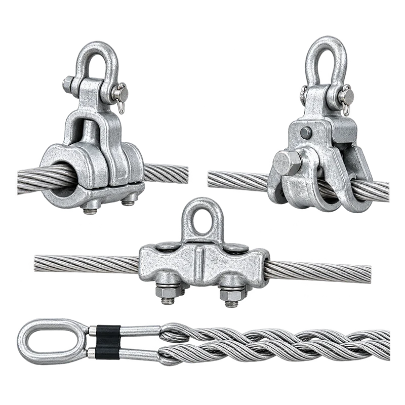
| 6 | Check suspension / dead-end hardware ratings match RTS | Fittings must not fail before cable |
For your ADSS product selection, browse our fiber optic cable range or contact the LX Cable engineering team for a project-specific tension calculation.

Preguntas frecuentes
What is the difference between RTS and MAT?
RTS is the calculated breaking force of the cable (the absolute mechanical limit). MAT is the maximum safe working tension under worst-case combined weather — typically 40 % of RTS. MAT guarantees zero fiber strain; RTS guarantees the cable will not break.
Why is EDS usually much lower than MAT?
EDS (16–25 % estrategia en tiempo real) represents the cable’s daily steady-state tension under calm, no-ice conditions. Because the cable lives at EDS 99 % of its service life, the aramid creep rate and fatigue damage at this level determine whether the fiber stays attenuation-free for 25+ años.
What happens if a supplier quotes only RTS without MAT and EDS?
You cannot do a proper sag-tension calculation. RTS alone tells you the cable will not snap in a lab test, but says nothing about whether the fiber will remain strain-free under your worst weather or how quickly it will creep over decades. Always require all three values before purchase.
Which standard governs ADSS tensile ratings?
Estándar IEEE 1222-2019 covers ADSS cable design and testing for installation on supply lines. CEI 60794-4-20 addresses fiber optic cables on power lines internationally. Both require RTS testing at ≥ 95 % of rated and fiber-strain limits at MAT.
Can I convert MAT directly to maximum span distance?
No single formula converts MAT to span. You need a sag-tension calculation that inputs cable weight per km, design wind pressure, radial ice thickness, and allowable sag for clearance. That output is compared against MAT. Our span design guide explains the inputs.


